Installation instructions for part #48505

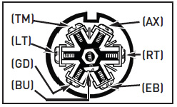
WIRE IDENTIFICATION /
IDENTIFICACIÓN DE LOS CABLES
(GD) = Ground / Tierra
(LT) = Left Turn / Direccional I zquierda
(TM) = Taillight / Luces traseras
(BU) = Backup / Reversa
(AX) = Auxiliary / Auxiliar
(RT) = Right Turn / Direccional D erecha
(EB) = Electric Brake / Eléctrico del Freno

INSTRUCTIONS:
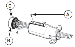
1. Loosen the set screw (A) and remove the terminal assembly (B) from housing. Route wiring through housing. Strip wires 1/4” and tightly secure them to the terminal assembly. It is important to attach wires to the terminal assembly in the same positions as found on the vehicle side 7-way socket. Leave 18” of slack between tow vehicle and trailer to allow trailer to
turn. Align terminal assembly keyway (C) with housing key and insert assembly into housing. Tighten set screw.
2. Plug trailer into vehicle and test all functions.
NOTE: Locate wires on vehicle by function only. Color coding is not standard with all manufacturers.
_____________________________________________________________________________
INSTRUCCIONES:
1. Afloje el tornillo (A) y saque el montaje de terminales (B) del conector. Dirija el cableado a través del conector. Desforre cada cable 1/4 de pulgada y asegúrelos firmemente al montaje. Es importante unir los cables en el montaje de terminales en la misma posición que tienen en el enchufe de 7 vías, en el lado del vehículo. Deje 18 pulgadas de holgura entre el vehículo y el remolque, para permitir al remolque dar vuelta. Alínee la ranura del montaje de terminales (C) con el conector e introduzca el montaje dentro del conector. Ajuste el tornillo.
2. Conecte al vehículo y pruebe todas las funciones.
NOTA: Localice los cables del vehículo por su función solamente. El código de colores no es el mismo para todos los fabricantes.